- Contents in this wiki are for entertainment purposes only
Field Array Pulse Injector: Difference between revisions
XenoEngineer (talk | contribs) No edit summary |
XenoEngineer (talk | contribs) |
||
| Line 2: | Line 2: | ||
=== NanoBolt Field Array Driver === | === NanoBolt Field Array Driver === | ||
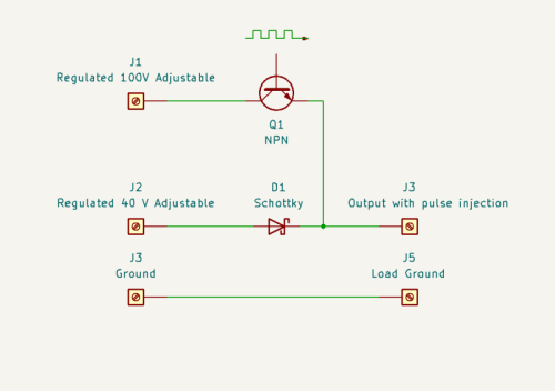
[[File:Pulse injector concept 800x563.png|left|500px|thumb|Schematic 1. The basic principle of NMR resonance is to create a background magnetic flux in copper resonator element with a steady direct electrical current (D.C.) into a resonator (load) element. A fast blocking diode (D1) allows a higher voltage pulse 'injected' into the load circuit connected at J3, between the blocking diode and the resonator element. In NMR jargon, J1 signal injects a B1 pulse-train over the B0 nuclear spin precessing flux created by current through J2.]] | |||
[[File:EPC2022 to TO-220 footprint adaptor.jpg|right|400px]] | [[File:EPC2022 to TO-220 footprint adaptor.jpg|right|400px]] | ||
In the [[Field Array]] prototype designs, transistor Q1 in Schematic 1 is replaced with quantum-enhanced FET technology (eGaN) by EPC (EPC2022). | |||
To best appreciate the switching speed of the eGaN, the circuit must be optimized to minimum inductance. The design facilitates optimized low-inductance for higher frequency operation of the switches when configured in a [[Resonant-X configuration]] (prototype chaotic power-logic-ring oscillator), by embedding the adaptor board of Illus. 1 within a solid copper conductor of sufficient diameter to allow a hollow center for connecting the circuit to the power stud, and receiving B0 current. Also on the body of the stud is a connector receiving the switching signal, which routes to the eGaN gate through the adaptor. | |||
Please standby for further open-sourced development. | |||
[[User:XenoEngineer|XenoEngineer]] —research and development by a talking simian 10:53, 30 September 2023 (UTC) | |||
<html> | |||
<a href="https://i.ebayimg.com/images/g/TSQAAOSwxblbUOQS/s-l1600.jpg"><img width="400px" src="https://i.ebayimg.com/images/g/TSQAAOSwxblbUOQS/s-l1600.jpg" /></a> | |||
<h3>Note: The eGaN drain connection (D on the top side) is plated-through to become the ground-plane of the back-side of the adaptor circuit.</h3> | |||
<h3>Note: 1 qty EPC2022 eGaN and two SMD resistors are required to complete this adaptor circuit.</h3> | |||
</html> | |||
</div> | |||
Revision as of 10:53, 30 September 2023
NanoBolt Field Array Driver

In the Field Array prototype designs, transistor Q1 in Schematic 1 is replaced with quantum-enhanced FET technology (eGaN) by EPC (EPC2022).
To best appreciate the switching speed of the eGaN, the circuit must be optimized to minimum inductance. The design facilitates optimized low-inductance for higher frequency operation of the switches when configured in a Resonant-X configuration (prototype chaotic power-logic-ring oscillator), by embedding the adaptor board of Illus. 1 within a solid copper conductor of sufficient diameter to allow a hollow center for connecting the circuit to the power stud, and receiving B0 current. Also on the body of the stud is a connector receiving the switching signal, which routes to the eGaN gate through the adaptor.
Please standby for further open-sourced development. XenoEngineer —research and development by a talking simian 10:53, 30 September 2023 (UTC)

