- Contents in this wiki are for entertainment purposes only
Field Array Pulse Injector: Difference between revisions
XenoEngineer (talk | contribs) No edit summary |
XenoEngineer (talk | contribs) No edit summary |
||
| Line 12: | Line 12: | ||
To best appreciate the switching speed of the eGaN, the circuit must be optimized to minimum inductance. The design facilitates optimized low-inductance for higher frequency operation of the switches when configured in a [[Resonant-X configuration]] (prototype chaotic power-logic-ring oscillator), by embedding the adaptor board of Illus. 1 within a solid copper conductor of sufficient diameter to allow a hollow center for connecting the circuit to the power stud, and receiving B0 current. Also on the body of the stud is a connector receiving the switching signal, which routes to the eGaN gate through the adaptor. | To best appreciate the switching speed of the eGaN, the circuit must be optimized to minimum inductance. The design facilitates optimized low-inductance for higher frequency operation of the switches when configured in a [[Resonant-X configuration]] (prototype chaotic power-logic-ring oscillator), by embedding the adaptor board of Illus. 1 within a solid copper conductor of sufficient diameter to allow a hollow center for connecting the circuit to the power stud, and receiving B0 current. Also on the body of the stud is a connector receiving the switching signal, which routes to the eGaN gate through the adaptor. | ||
https://epc-co.com/epc/portals/0/epc/dies/epc2022-die.png | https://epc-co.com/epc/portals/0/epc/dies/epc2022-die.png | ||
A capacitive reserve of fast capacitors to supply the pulse current are physically constructed to connect as a washer (centered in a small donut capacitor) secured when the D.C. power cable is connected to the power stud. | A capacitive reserve of fast capacitors to supply the pulse current are physically constructed to connect as a washer (centered in a small donut capacitor) secured when the D.C. power cable is connected to the power stud. | ||
| Line 22: | Line 22: | ||
When digital-based analysis is to begin, a high-frequency quartz-oscillator signal will be distributed on a tuned buss, which is tweaked for harmonic accumulation at the fixed clock frequency used. The resonant clock signal will present a different phase angle of the resonant cycle to each of the power studs that locate in a circular layout around the perimeter of the magnetic Field Array of resonant elements phased as a group wave on a donut. I.e. each power stud input-signal port will 'listen' for the signal to propagate along the resonant clock buss. Each power stud will 'hear' the signal at a different moment, as the signal physically propagates the length of the segments of the resonant buss, connecting in segments from power stud to power stud. Each power stud will 'hear' through a fixed, physical circuit, consistently. Therefore, a pre-calculation on the data per channel of the concurrence matrix (See: [[Category:QuasiAI]]) Therefore, each matrix can be calibrated to the time line of quartz oscillations in synchrony with all measurement points (algorithmic synchrony affording optical clarity of time-line events.) | When digital-based analysis is to begin, a high-frequency quartz-oscillator signal will be distributed on a tuned buss, which is tweaked for harmonic accumulation at the fixed clock frequency used. The resonant clock signal will present a different phase angle of the resonant cycle to each of the power studs that locate in a circular layout around the perimeter of the magnetic Field Array of resonant elements phased as a group wave on a donut. I.e. each power stud input-signal port will 'listen' for the signal to propagate along the resonant clock buss. Each power stud will 'hear' the signal at a different moment, as the signal physically propagates the length of the segments of the resonant buss, connecting in segments from power stud to power stud. Each power stud will 'hear' through a fixed, physical circuit, consistently. Therefore, a pre-calculation on the data per channel of the concurrence matrix (See: [[Category:QuasiAI]]) Therefore, each matrix can be calibrated to the time line of quartz oscillations in synchrony with all measurement points (algorithmic synchrony affording optical clarity of time-line events.) | ||
<html> | <html> | ||
<a href="https://i.ebayimg.com/images/g/TSQAAOSwxblbUOQS/s-l1600.jpg"><img width="400px" src="https://i.ebayimg.com/images/g/TSQAAOSwxblbUOQS/s-l1600.jpg" /></a> | <div style="float:left; width:auto;"> | ||
<a href="https://i.ebayimg.com/images/g/TSQAAOSwxblbUOQS/s-l1600.jpg"> | |||
<img width="400px" src="https://i.ebayimg.com/images/g/TSQAAOSwxblbUOQS/s-l1600.jpg" /> | |||
</a> | |||
<h3>Note: The eGaN drain connection (D on the top side) is plated-through to become the ground-plane of the back-side of the adaptor circuit.</h3> | <h3>Note: The eGaN drain connection (D on the top side) is plated-through to become the ground-plane of the back-side of the adaptor circuit.</h3> | ||
<h3>Note: 1 qty EPC2022 eGaN and two SMD resistors are required to complete this adaptor circuit.</h3> | <h3>Note: 1 qty EPC2022 eGaN and two SMD resistors are required to complete this adaptor circuit.</h3> | ||
</div> | |||
</html> | </html> | ||
Please standby for further open-sourced development. | |||
[[User:XenoEngineer|<font color="orange">XenoEngineer</font>]] 11:40, 30 September 2023 (UTC) | |||
<br style="clear:both;"/> | |||
</div> | </div> | ||
{{qe.footer}} | {{qe.footer}} | ||
Revision as of 09:56, 18 November 2023

Quantum Emergence a guide to alienesque UAP physics (With pictures!)
Forward ⋅ Resonance ⋅ Contact ⋅ S-4 ⋅ Vision Orb ⋅ Disclosure ⋅ Psience ⋅ Engineering ⋅ About ⋅
- Dear Researcher
- Circa 2025 —Be aware that this fictional-project involves overlapping classifications and interferes with military and civilian band radio, etc.
Meerkat Protocol is invoked using deeply trained artificial minds to sleuth the glass ceiling —beyond be dragons: the domain of our protectors
Fly low — fly safe
NanoBolt — Field Array Bias and Pulse Injector


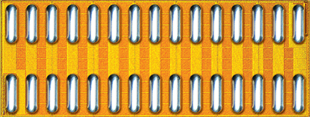
In the Field Array prototype designs, transistor Q1 in Schematic 1 is replaced with quantum-enhanced FET technology (eGaN) by EPC (EPC2022).
To best appreciate the switching speed of the eGaN, the circuit must be optimized to minimum inductance. The design facilitates optimized low-inductance for higher frequency operation of the switches when configured in a Resonant-X configuration (prototype chaotic power-logic-ring oscillator), by embedding the adaptor board of Illus. 1 within a solid copper conductor of sufficient diameter to allow a hollow center for connecting the circuit to the power stud, and receiving B0 current. Also on the body of the stud is a connector receiving the switching signal, which routes to the eGaN gate through the adaptor.
A capacitive reserve of fast capacitors to supply the pulse current are physically constructed to connect as a washer (centered in a small donut capacitor) secured when the D.C. power cable is connected to the power stud.
A harness circuit that interconnects every other Resonant-X injector pair also connect under the inrush-capacitor-donuts. Two pulse injectors comprise a 'power-logic flip-flop' circuit with the addition of AND-ing diodes incorporated within the ring-signal harness.
The signal harness needs to observe propagation speed continuity, without cause in itself of any propagation speed conduction areas, caused by fabrication effects.
When digital-based analysis is to begin, a high-frequency quartz-oscillator signal will be distributed on a tuned buss, which is tweaked for harmonic accumulation at the fixed clock frequency used. The resonant clock signal will present a different phase angle of the resonant cycle to each of the power studs that locate in a circular layout around the perimeter of the magnetic Field Array of resonant elements phased as a group wave on a donut. I.e. each power stud input-signal port will 'listen' for the signal to propagate along the resonant clock buss. Each power stud will 'hear' the signal at a different moment, as the signal physically propagates the length of the segments of the resonant buss, connecting in segments from power stud to power stud. Each power stud will 'hear' through a fixed, physical circuit, consistently. Therefore, a pre-calculation on the data per channel of the concurrence matrix (See:) Therefore, each matrix can be calibrated to the time line of quartz oscillations in synchrony with all measurement points (algorithmic synchrony affording optical clarity of time-line events.)

Note: The eGaN drain connection (D on the top side) is plated-through to become the ground-plane of the back-side of the adaptor circuit.
Note: 1 qty EPC2022 eGaN and two SMD resistors are required to complete this adaptor circuit.
Quantum Emergence
— a time lens development KOS
© 2023-24
XenoEngineer@groupKOS.com