- Contents in this wiki are for entertainment purposes only
Field Array Pulse Injector
NanoBolt Field Array Driver

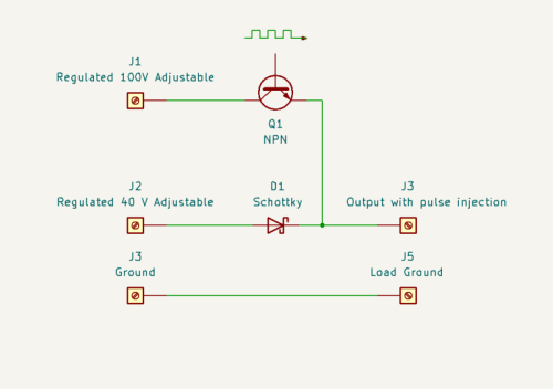
In the Field Array prototype designs, transistor Q1 in Schematic 1 is replaced with quantum-enhanced FET technology (eGaN) by EPC (EPC2022).
To best appreciate the switching speed of the eGaN, the circuit must be optimized to minimum inductance. The design facilitates optimized low-inductance for higher frequency operation of the switches when configured in a Resonant-X configuration (prototype chaotic power-logic-ring oscillator), by embedding the adaptor board of Illus. 1 within a solid copper conductor of sufficient diameter to allow a hollow center for connecting the circuit to the power stud, and receiving B0 current. Also on the body of the stud is a connector receiving the switching signal, which routes to the eGaN gate through the adaptor.
Please standby for further open-sourced development. XenoEngineer —research and development by a talking simian 10:53, 30 September 2023 (UTC)

