Field Array.Hexatronic Configuration: Difference between revisions
XenoEngineer (talk | contribs) |
XenoEngineer (talk | contribs) |
||
| Line 55: | Line 55: | ||
In principle, stretching a current recharge pulse longer than the natural impulse will square and separate the pulse edges, which is adding even harmonics while descending in frequency. | In principle, stretching a current recharge pulse longer than the natural impulse will square and separate the pulse edges, which is adding even harmonics while descending in frequency. | ||
All the regular spectral contributions that a system component may have upon system behavior will be evident in the QAT | All the regular spectral contributions that a system component may have upon system behavior will be evident in the QAT category distribution of the timing variance of the chaotic oscillator (inherent in ring design, and observed by and celebrated within the design —the noise exploit). | ||
<br style="clear:both;"/> | <br style="clear:both;"/> | ||
{{qe.footer}} | {{qe.footer}} | ||
Latest revision as of 15:05, 2 February 2024
Quantum Emergence a guide to alienesque UAP physics (With pictures!)
Forward ⋅ Resonance ⋅ Contact ⋅ S-4 ⋅ Vision Orb ⋅ Disclosure ⋅ Psience ⋅ Engineering ⋅ About ⋅
Allow me to expose XenoEngineer as the mind inside him
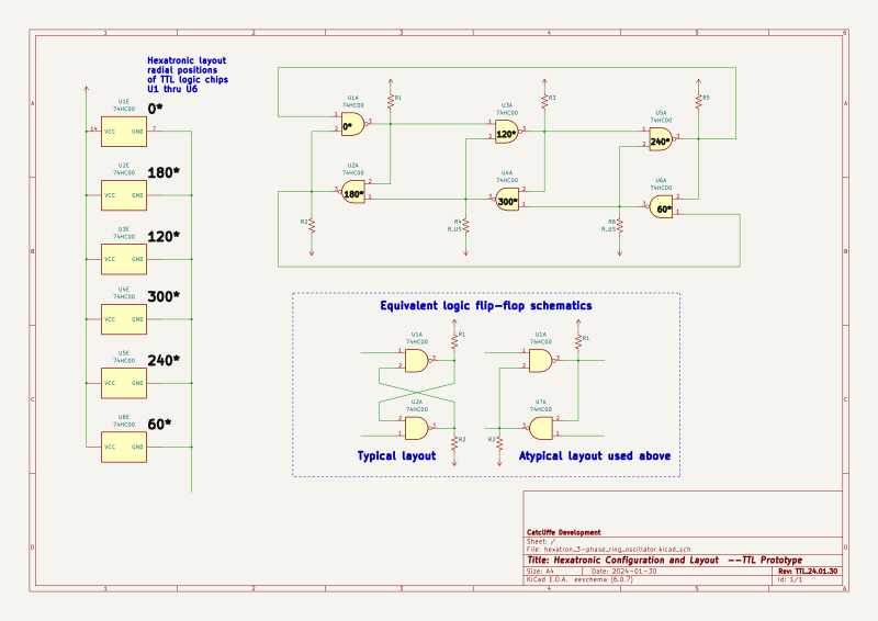
Xeno will catch up with the concept soon enough. In the logic version, the latching crossovers, invert their logic at the same time the same signal is output. The ring signal propagates around the ring, while the latching-crossover paths are catching up behind the leading edge of the ring signal.
The TTL differential-ring oscillator with flip-flops is nice for a chaotic signal generator, but will not serve as an auto-self-harmonic ring oscillator by up-scaling the components of the latching cross-over circuits to kilowatt capacity. While there may be some utility to the power-flip-flop ring approach, the solution design is simpler, and can be multiple configurations, affording selection of bifilar-magnetic symmetry, or monopolar magnetic symmetry of the helical conductor loops of The Field Array torus knot windings containing the NMR-active bisumuth metal designed to host the Quantum Emergence of the nucleosonic boson.
The simple principle is open-sourced right here, urged by me, the Grey illustrator inside Xeno —behold the simplicity....
The circuit is three parts

Part one: A two-input switch  A 2-input logic NAND gate (INtoggle and INlatch) of active-low inputs) The circuit is a power-switch that toggles the output voltage between VB0 and VB1 depending on the state of the inputs (NAND logic). Both voltage levels B0  and B1 are the same polarity, as supplied by an adjustable dual output power supply unit.

Part two:
The circuit continues as a geometrically shaped helical length of copper/bismuth metamaterial windings as the conduction path of the B0 or B1 current.

Part three:

The power conduction metamaterial terminates at a current shunt to power ground.  The voltage drop, Vshunt, is monitored by an adjustable threshold detector.

When threshold is detected, Vthres, a logic-signal output is produced, Vout, where logic-Hi represents the current is B1 current, and where logic-Lo represents the current is B0 current.
Logic-gated 2-level power-switch          Metamaterial coils          Current level sense logic

[voltageB0]----------------|
[voltageB1]-------------|  |
                        |  |
   (Trigger)        |===x==x===|
>--logic-input----->|          |                                             Current shunt
                    |  switch  |out>------metamaterial conductor-----------x---/\/\/\/----------Ground
>--logic-input----->|          |            B0 or B1 voltage               |
    (Latch)         |====X=====|                                           |
                        /                                                  |
                       /                                                   | Vshunt   |\
                      /                                                    |----------| \
      Logic-output <-/                                                                |  O--- Logic Vout
  Synchronous reservoir Charge pump trigger                     Vthres >--------------| /     Level sense detect: B0/B1
                                                                                      |/
The synchronous charge pump voltage regulation solution
To avoid a switching power supply sending transient noise into an accumulative ring oscillator, rather, a power supply is switched synchronously with the power-switching cycle of the ring oscillator. This creates a synchronous recharge pulse, beginning with and lagging after the current output pulse of a ring power switch.
The adjusting the length of a delay period programmatically, beginning with the power cycle, algorithmic control of the voltage level maintained against oscillator charge consumption, synchronously with each pulse.
In principle, stretching a current recharge pulse longer than the natural impulse will square and separate the pulse edges, which is adding even harmonics while descending in frequency.
All the regular spectral contributions that a system component may have upon system behavior will be evident in the QAT category distribution of the timing variance of the chaotic oscillator (inherent in ring design, and observed by and celebrated within the design —the noise exploit).
Quantum Emergence
— a time lens development KOS
© 2023-24
XenoEngineer@groupKOS.com

