Field Array Pulse Injector: Difference between revisions
XenoEngineer (talk | contribs) No edit summary |
XenoEngineer (talk | contribs) |
||
| (13 intermediate revisions by the same user not shown) | |||
| Line 1: | Line 1: | ||
{{qe.header}} | {{qe.header}} | ||
{{HeaderFieldArray}} | {{HeaderFieldArray}} | ||
=<font color="red"><big>'''{{PAGENAME}}'''</big></font>= | |||
<div style="float:right; width:425px;"> | |||
__TOC__ | |||
</div> | |||
=={{lime24|loose notes it would take an AI to make sense of (standby)}}== | |||
===<font color="lime">what it is</font>=== | |||
The pulse injector is the power element of a ring oscillator/amplifier. | |||
The injector is a very high-speed power transistor that is controlled by an INVERTING two-input logic-gate. To create a ring oscillation, connect a ring of inverting amplifiers in odd numbers. (Even numbers don't oscillate.) | |||
To create a segmented, chaotic oscillation, as a certain self-oscillating design (just add D.C. power), the two-input gates afford a design of dual-logic-ring oscillations. The duality is implemented in principle as a logic flip-flop, which will latch in an ON-OFF state, or an OFF-ON state. | |||
A 3-phase ring oscillator, implemented as a ring of three flip-flop logic configurations, contains six-quantity latching-signal conductors. These conductors are braided on a donut in a fashion to produce a continuous change in high-amperage conduction patterns, moving tangentially over the copper windings covering the donut surface. | |||
The continuous magnetic density wave on a donut is made possible geometrically using torus knot windings. Fifty percent of the knot groupings create a sorted order of the phase windings of the torus group. Self-sorting knot groups for a Fibonacci number knot winding ratio of 13:8 are 3-, 5-, 11-, and 13-count of knots on a donut. | |||
== {{lime24|Pulse Injector layout around the donut}} == | |||
The injectors that energize a 13:8 knotted winding scheme, as a 3-group of copper windings (3-phase), '''are arranged in a circle''', encircling the periphery of the donut, around the outside of the torus surface of the copper knotted windings. They belt the equator of the donut. | |||
The inter-phase connections create a daisy-chain configuration of wire conductors, which have least effect upon the symmetry of the whole when the daisy-chain forms daisy-petals on a plane intersecting the injectors encircling the donut. | |||
== <font color="red">Other oscillator configurations with inverting, dual-input power-pulse injectors</font> == | |||
Any number of phase-counts can be implemented artificially, by algorithmic control. Algorithmic simulation of a two-input inverting gate is trivial, and when parallelized to create a logic state machine for extremely fast oscillator frequencies are easily implemented as discrete hardware of a two-input device; realized as a 1000 Watt power injector. A 2-input NAND gate with a 1000 kilowatt totem biased up from ground to produce D.C. current as adjustment of B0 to change the the spin-precession frequency of the conductor metamaterial. | |||
'''Dear researcher: Please be aware that nuclear magnetic resonance can be enticed as a continuous resonance against the nuclear magnetic flux. This would be CW NMR. The Quantum Emergence jargon, and Field Array theme, are both all about a controlled standing continous wave resonance serving to scan the atom's womb for the alienesque affordance humans have overlooked for want of citational elitism in competitive fields of study. You know how we are.''' | |||
=== <font color="orange">The affordance is a nucleosonic resonance</font> === | |||
And therein by resonating with quantum units will affect the rate of quantum fulfillment of the space-time timeline, also quipped as space-timing. | |||
A macro-emergence of the nucleosonic periodic, and energy accumulation against the affected matter lattice, hosting the nucleosonic energy accumulation, which is simultaneously retarding the rate things age at the quantum level, on a gradient through space-timing toward center of the Field Array producing this so called dimple in time. | |||
=== <font color="red"> NanoBolt — Field Array Bias and Pulse Injector</font> === | === <font color="red"> NanoBolt — Field Array Bias and Pulse Injector</font> === | ||
| Line 8: | Line 43: | ||
[[File:EPC2022 to TO-220 footprint adaptor.jpg|right|400px]] | [[File:EPC2022 to TO-220 footprint adaptor.jpg|right|400px]] | ||
In | In [[The Field Array|<font color="orange">The Field Array</font>]] prototype designs, transistor Q1 in Schematic 1 is replaced with quantum-enhanced FET technology (eGaN) by EPC (EPC2022). | ||
To best appreciate the switching speed of the eGaN, the circuit must be optimized to minimum inductance. The design facilitates optimized low-inductance for higher frequency operation of the switches when configured in a [[Resonant-X configuration]] (prototype chaotic power-logic-ring oscillator), by embedding the adaptor board of Illus. 1 within a solid copper conductor of sufficient diameter to allow a hollow center for connecting the circuit to the power stud, and receiving B0 current. Also on the body of the stud is a connector receiving the switching signal, which routes to the eGaN gate through the adaptor. | To best appreciate the switching speed of the eGaN, the circuit must be optimized to minimum inductance. The design facilitates optimized low-inductance for higher frequency operation of the switches when configured in a [[Resonant-X configuration]] (prototype chaotic power-logic-ring oscillator), by embedding the adaptor board of Illus. 1 within a solid copper conductor of sufficient diameter to allow a hollow center for connecting the circuit to the power stud, and receiving B0 current. Also on the body of the stud is a connector receiving the switching signal, which routes to the eGaN gate through the adaptor. | ||
https://epc-co.com/epc/portals/0/epc/dies/epc2022-die.png | https://epc-co.com/epc/portals/0/epc/dies/epc2022-die.png | ||
A capacitive reserve of fast capacitors to supply the pulse current are physically constructed to connect as a washer (centered in a small donut capacitor) secured when the D.C. power cable is connected to the power stud. | A capacitive reserve of fast capacitors to supply the pulse current are physically constructed to connect as a washer (centered in a small donut capacitor) secured when the D.C. power cable is connected to the power stud. | ||
| Line 18: | Line 53: | ||
A harness circuit that interconnects every other Resonant-X injector pair also connect under the inrush-capacitor-donuts. Two pulse injectors comprise a 'power-logic flip-flop' circuit with the addition of AND-ing diodes incorporated within the ring-signal harness. | A harness circuit that interconnects every other Resonant-X injector pair also connect under the inrush-capacitor-donuts. Two pulse injectors comprise a 'power-logic flip-flop' circuit with the addition of AND-ing diodes incorporated within the ring-signal harness. | ||
The signal harness needs to observe propagation speed continuity, without cause in itself of any propagation | The signal harness needs to observe propagation speed continuity, time balanced, without cause in itself of any propagation reflection areas, caused by fabrication effects. | ||
When digital-based analysis is to begin, a high-frequency quartz-oscillator signal will be distributed on a tuned buss, which is tweaked for harmonic accumulation at the fixed clock frequency used. The resonant clock signal will present a different phase angle of the resonant cycle to each of the power studs that locate in a circular layout around the perimeter of the magnetic Field Array of resonant elements phased as a group wave on a donut. I.e. each power stud input-signal port will 'listen' for the signal to propagate along the resonant clock buss. Each power stud will 'hear' the signal at a different moment, as the signal physically propagates the length of the segments of the resonant buss, connecting in segments from power stud to power stud. Each power stud will 'hear' through a fixed, physical circuit, consistently. Therefore, a pre-calculation on the data per channel of the concurrence matrix (See: [[Category:QuasiAI]]) would afford a time-balance pre-tuning algorithmically, wherein each matrix can be calibrated to the time line of quartz oscillations in synchrony with all measurement points of a sampling moment (algorithmic synchrony affording optical clarity of time-line events.) | |||
<div style="float:left; width:auto; color:orange;"> | |||
<html><img width="800px" src="https://i.ebayimg.com/images/g/TSQAAOSwxblbUOQS/s-l1600.jpg" /></html> | |||
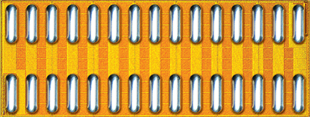
;Note: The eGaN drain connection (D on the top side) is plated-through to become the ground-plane of the back-side of the adaptor circuit. | |||
;Note: 1 qty EPC2022 eGaN and two SMD resistors are required to complete this adaptor circuit. | |||
</div> | |||
;Please standby for further open-sourced development. | |||
[[User:XenoEngineer|<font color="orange">XenoEngineer</font>]] 11:40, 30 September 2023 (UTC) | [[User:XenoEngineer|<font color="orange">XenoEngineer</font>]] 11:40, 30 September 2023 (UTC) | ||
< | <br style="clear:both;"/> | ||
</div> | </div> | ||
{{qe.footer}} | {{qe.footer}} | ||
Latest revision as of 13:38, 20 December 2023

Quantum Emergence a guide to alienesque UAP physics (With pictures!)
Forward ⋅ Resonance ⋅ Contact ⋅ S-4 ⋅ Vision Orb ⋅ Disclosure ⋅ Psience ⋅ Engineering ⋅ About ⋅
Field Array Pulse Injector
loose notes it would take an AI to make sense of (standby)
what it is
The pulse injector is the power element of a ring oscillator/amplifier.
The injector is a very high-speed power transistor that is controlled by an INVERTING two-input logic-gate. To create a ring oscillation, connect a ring of inverting amplifiers in odd numbers. (Even numbers don't oscillate.)
To create a segmented, chaotic oscillation, as a certain self-oscillating design (just add D.C. power), the two-input gates afford a design of dual-logic-ring oscillations. The duality is implemented in principle as a logic flip-flop, which will latch in an ON-OFF state, or an OFF-ON state.
A 3-phase ring oscillator, implemented as a ring of three flip-flop logic configurations, contains six-quantity latching-signal conductors. These conductors are braided on a donut in a fashion to produce a continuous change in high-amperage conduction patterns, moving tangentially over the copper windings covering the donut surface.
The continuous magnetic density wave on a donut is made possible geometrically using torus knot windings. Fifty percent of the knot groupings create a sorted order of the phase windings of the torus group. Self-sorting knot groups for a Fibonacci number knot winding ratio of 13:8 are 3-, 5-, 11-, and 13-count of knots on a donut.
Pulse Injector layout around the donut
The injectors that energize a 13:8 knotted winding scheme, as a 3-group of copper windings (3-phase), are arranged in a circle, encircling the periphery of the donut, around the outside of the torus surface of the copper knotted windings. They belt the equator of the donut.
The inter-phase connections create a daisy-chain configuration of wire conductors, which have least effect upon the symmetry of the whole when the daisy-chain forms daisy-petals on a plane intersecting the injectors encircling the donut.
Other oscillator configurations with inverting, dual-input power-pulse injectors
Any number of phase-counts can be implemented artificially, by algorithmic control. Algorithmic simulation of a two-input inverting gate is trivial, and when parallelized to create a logic state machine for extremely fast oscillator frequencies are easily implemented as discrete hardware of a two-input device; realized as a 1000 Watt power injector. A 2-input NAND gate with a 1000 kilowatt totem biased up from ground to produce D.C. current as adjustment of B0 to change the the spin-precession frequency of the conductor metamaterial.
Dear researcher: Please be aware that nuclear magnetic resonance can be enticed as a continuous resonance against the nuclear magnetic flux. This would be CW NMR. The Quantum Emergence jargon, and Field Array theme, are both all about a controlled standing continous wave resonance serving to scan the atom's womb for the alienesque affordance humans have overlooked for want of citational elitism in competitive fields of study. You know how we are.
The affordance is a nucleosonic resonance
And therein by resonating with quantum units will affect the rate of quantum fulfillment of the space-time timeline, also quipped as space-timing.
A macro-emergence of the nucleosonic periodic, and energy accumulation against the affected matter lattice, hosting the nucleosonic energy accumulation, which is simultaneously retarding the rate things age at the quantum level, on a gradient through space-timing toward center of the Field Array producing this so called dimple in time.
NanoBolt — Field Array Bias and Pulse Injector


In The Field Array prototype designs, transistor Q1 in Schematic 1 is replaced with quantum-enhanced FET technology (eGaN) by EPC (EPC2022).
To best appreciate the switching speed of the eGaN, the circuit must be optimized to minimum inductance. The design facilitates optimized low-inductance for higher frequency operation of the switches when configured in a Resonant-X configuration (prototype chaotic power-logic-ring oscillator), by embedding the adaptor board of Illus. 1 within a solid copper conductor of sufficient diameter to allow a hollow center for connecting the circuit to the power stud, and receiving B0 current. Also on the body of the stud is a connector receiving the switching signal, which routes to the eGaN gate through the adaptor.
A capacitive reserve of fast capacitors to supply the pulse current are physically constructed to connect as a washer (centered in a small donut capacitor) secured when the D.C. power cable is connected to the power stud.
A harness circuit that interconnects every other Resonant-X injector pair also connect under the inrush-capacitor-donuts. Two pulse injectors comprise a 'power-logic flip-flop' circuit with the addition of AND-ing diodes incorporated within the ring-signal harness.
The signal harness needs to observe propagation speed continuity, time balanced, without cause in itself of any propagation reflection areas, caused by fabrication effects.
When digital-based analysis is to begin, a high-frequency quartz-oscillator signal will be distributed on a tuned buss, which is tweaked for harmonic accumulation at the fixed clock frequency used. The resonant clock signal will present a different phase angle of the resonant cycle to each of the power studs that locate in a circular layout around the perimeter of the magnetic Field Array of resonant elements phased as a group wave on a donut. I.e. each power stud input-signal port will 'listen' for the signal to propagate along the resonant clock buss. Each power stud will 'hear' the signal at a different moment, as the signal physically propagates the length of the segments of the resonant buss, connecting in segments from power stud to power stud. Each power stud will 'hear' through a fixed, physical circuit, consistently. Therefore, a pre-calculation on the data per channel of the concurrence matrix (See:) would afford a time-balance pre-tuning algorithmically, wherein each matrix can be calibrated to the time line of quartz oscillations in synchrony with all measurement points of a sampling moment (algorithmic synchrony affording optical clarity of time-line events.)

- Note
- The eGaN drain connection (D on the top side) is plated-through to become the ground-plane of the back-side of the adaptor circuit.
- Note
- 1 qty EPC2022 eGaN and two SMD resistors are required to complete this adaptor circuit.
- Please standby for further open-sourced development.
XenoEngineer 11:40, 30 September 2023 (UTC)
Quantum Emergence
— a time lens development KOS
© 2023-24
XenoEngineer@groupKOS.com