- Contents in this wiki are for entertainment purposes only
Dev:NSROS.System: Difference between revisions
Jump to navigation
Jump to search

XenoEngineer (talk | contribs) |
XenoEngineer (talk | contribs) mNo edit summary |
||
| Line 5: | Line 5: | ||
== {{lime24|The system}} == | == {{lime24|The system}} == | ||
=== | === Engineered in accord with [[Quantum Emergence.Cover|alternate physics of deterministic-quantum coherence]] === | ||
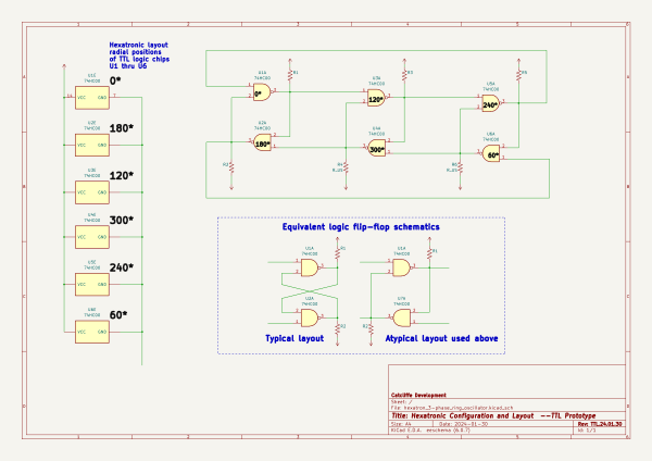
=== The Differential Logic Ring Oscillator === | === The Differential Logic Ring Oscillator === | ||
The differential-signal are the Q and Q~ (Q-not) outputs of a common logic circuit flip-flop. | The differential-signal are the Q and Q~ (Q-not) outputs of a common logic circuit flip-flop. | ||
[[|left| | [[File:Hexatronic configuration and layout--TTL Prototype.2024.01.30.png|left|600px]] | ||
The Q and Q~ outputs are connected to the Set and Reset inputs of the simple logic-connection of a 2-input, inverting output NAND gate (active low) as a latching 'flip-flop'. | The Q and Q~ outputs are connected to the Set and Reset inputs of the simple logic-connection of a 2-input, inverting output NAND gate (active low) as a latching 'flip-flop'. | ||
Revision as of 15:40, 23 September 2024

The Nucleo-Sonic Ring Oscillator System
phased magnetic array for tuning magnetic density wave velocity CW NMR activation as the phase-space compeller of the nucleo-phonon at system resonance by XenoEngineer
Overview ∞ System ∞ Hexatronic Logic Ring ∞ High-Frequency Operation ∞ Resonators ∞ Regularity Analysis ∞ Cognitive Potential ∞ About ∞ References ∞
The system
Engineered in accord with alternate physics of deterministic-quantum coherence
The Differential Logic Ring Oscillator
The differential-signal are the Q and Q~ (Q-not) outputs of a common logic circuit flip-flop.

The Q and Q~ outputs are connected to the Set and Reset inputs of the simple logic-connection of a 2-input, inverting output NAND gate (active low) as a latching 'flip-flop'. [[|right|600px]]
Power
Telemetry and Control
Analysis
© XenoEngineer November 2023